[match_prediction match_id="3"]

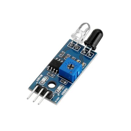
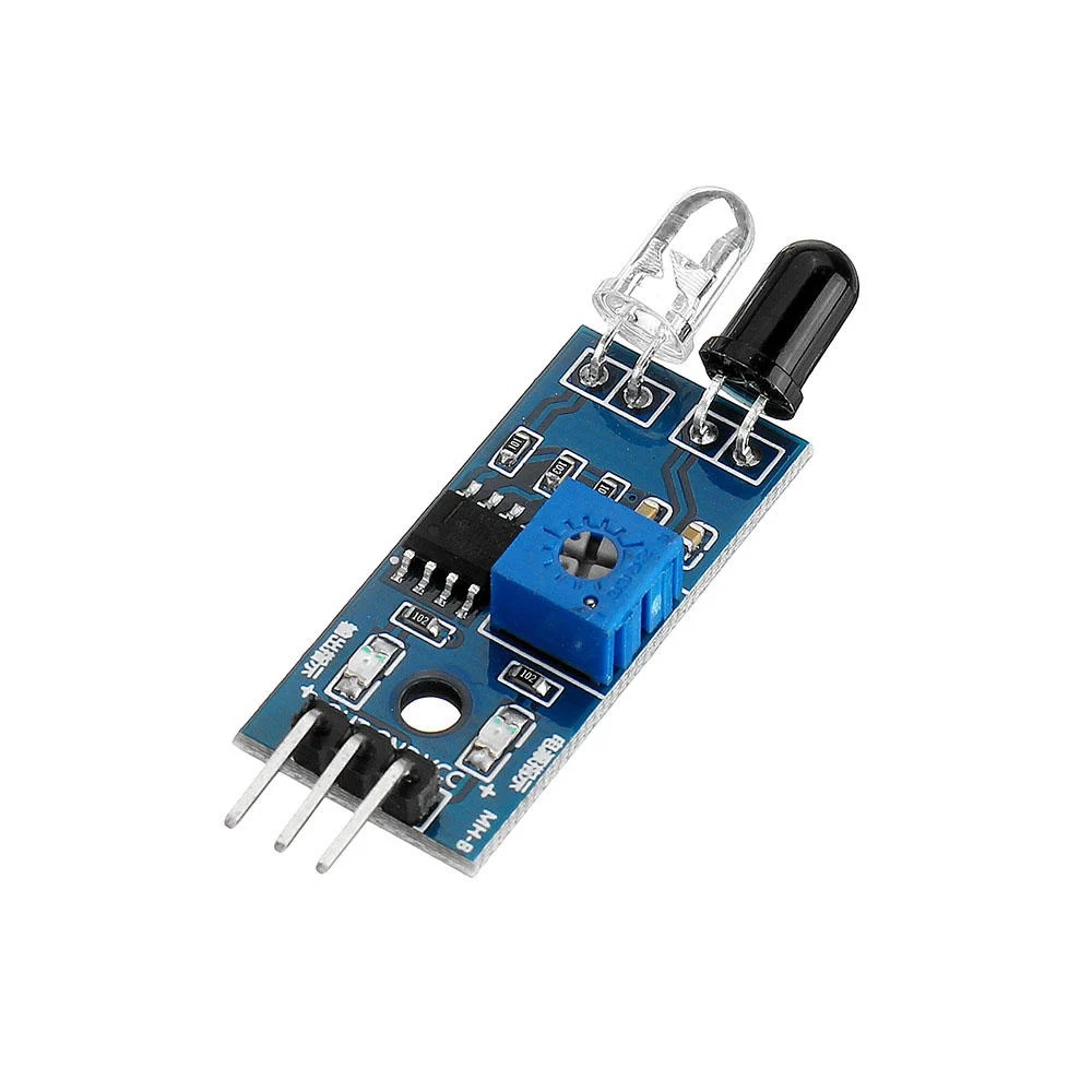
IR Sensor Infrared Obstacle Avoidance Module

  1. Detection distance: 2 ~ 30cm
  2. Detection angle: 35 °
  3. Comparator chip: LM393
  4. 3mm screw holes for easy mounting
SKU: AB072 Categories: , Tag:

35,00 EGP

12 People watching this product now!

Description

Infrared Obstacle Avoidance IR Sensor Module (Active Low) has a pair of infrared transmitting and receiving tubes. When the transmitted light waves are reflected back, the reflected IR waves will be received by the receiver tube. The onboard comparator circuitry does the processing and the green indicator LED comes to life.

The module features a 3 wire interface with Vcc, GND, and an OUTPUT pin on its tail. It works fine with 3.3 to 5V levels. Upon hindrance/reflectance, the output pin gives out a digital signal (a low-level signal). The onboard preset helps to fine-tune the range of operation, the effective distance range is 2cm to 30cm.


Features:

  1. Easy to assemble and use
  2. Onboard detection indication
  3. The effective distance range of 2cm to 30cm
  4. A preset knob to fine-tune distance range
  5. If there is an obstacle, the indicator lights on the circuit board.

Package Includes :

1 x Infrared Obstacle Avoidance IR Sensor Module (Active Low)

🔌
Pin Connections
1 Table
Pin Connections Table 1
Arduino UnoIR Obstacle SensorConnection Details
5VVCCPower supply for the IR sensor
GNDGNDCommon ground
Digital Pin 2 (D2)OUT / DODigital output signal from sensor (Supports Interrupts)
📟
IR Sensor Infrared Obstacle Avoidance Module
2 Examples • C/C++
Method 1: Basic Digital Polling
Method 2: Hardware Interrupts
Code Comments:
This section uses basic digitalRead() polling in the main loop to check the sensor state.
📄 File: method_1:_basic_digital_polling.inoArduino Uno
1268 characters
1/*
2 * ekostra.com
3 * ekostra electronics store in egypt
4 */
5
6// Define the pins connected to the IR sensor and LED
7const int irSensorPin = 2; // IR sensor OUT pin connected to Digital Pin 2
8const int ledPin = 13; // Built-in LED on Digital Pin 13
9
10// Variable to store the sensor state
11int sensorState = 0;
12
13void setup() {
14 // Initialize serial communication at 9600 bits per second
15 Serial.begin(9600);
16
17 // Set the IR sensor pin as an input to read signals
18 pinMode(irSensorPin, INPUT);
19
20 // Set the LED pin as an output for visual feedback
21 pinMode(ledPin, OUTPUT);
22
23 Serial.println("IR Sensor Polling Started");
24}
25
26void loop() {
27 // Read the current state of the IR sensor
28 // Note: Most IR obstacle sensors pull the line LOW when an obstacle is detected
29 sensorState = digitalRead(irSensorPin);
30
31 // Check if the sensor state is LOW (obstacle detected)
32 if (sensorState == LOW) {
33 // Turn on the built-in LED to indicate an obstacle is present
34 digitalWrite(ledPin, HIGH);
35 Serial.println("Obstacle Detected!");
36 } else {
37 // Turn off the LED when the path is clear
38 digitalWrite(ledPin, LOW);
39 Serial.println("Path Clear");
40 }
41
42 // Small delay to stabilize sensor readings and prevent serial flooding
43 delay(100);
44}
Code Comments:
This advanced method uses an Interrupt Service Routine (ISR) so the Arduino doesn't have to constantly poll the sensor in the main loop.
📄 File: method_2:_hardware_interrupts.inoArduino Uno
1524 characters
1/*
2 * ekostra.com
3 * ekostra electronics store in egypt
4 */
5
6// Define the pins
7// Pin 2 is used because it supports external hardware interrupts on the Arduino Uno
8const int irInterruptPin = 2;
9const int ledPin = 13;
10
11// Volatile boolean variable since it is modified inside an Interrupt Service Routine (ISR)
12volatile bool obstacleDetected = false;
13
14// Interrupt Service Routine (ISR) function
15// This function runs automatically independent of the main loop when the pin state changes
16void handleObstacle() {
17 // Read the pin state directly during the interrupt
18 if (digitalRead(irInterruptPin) == LOW) {
19 obstacleDetected = true; // Obstacle is currently present
20 } else {
21 obstacleDetected = false; // Obstacle has been removed
22 }
23}
24
25void setup() {
26 // Initialize serial monitor
27 Serial.begin(9600);
28
29 // Configure pins for input and output
30 pinMode(irInterruptPin, INPUT);
31 pinMode(ledPin, OUTPUT);
32
33 // Attach the interrupt to the sensor pin
34 // 'CHANGE' triggers the ISR whenever the pin toggles from HIGH to LOW or LOW to HIGH
35 attachInterrupt(digitalPinToInterrupt(irInterruptPin), handleObstacle, CHANGE);
36
37 Serial.println("IR Sensor Interrupt Mode Started");
38}
39
40void loop() {
41 // The main loop only checks the flag updated by the ISR
42 // This frees up the loop to run other non-blocking code!
43 if (obstacleDetected) {
44 digitalWrite(ledPin, HIGH);
45 } else {
46 digitalWrite(ledPin, LOW);
47 }
48
49 // Main loop logic can continue here without waiting for the sensor
50 delay(50);
51}
This project demonstrates two methods for interfacing an IR Obstacle Avoidance sensor with an Arduino Uno: standard digital polling and hardware interrupts.
[acf_vc_integrator get_field_data_from="" field_group="25154" field_from_25154="field_694d5bea250d3" show_label="default" align="default" gallery_columns="" gm_show_placecard="default" gm_map_type_control="default" gm_fullscreen_control="default" gm_street_view_control="default" gm_zoom_control="default" gm_scale="default" hidden_field_name="ARDUINO CODE"]
هذا الوصف والمواصفات تمت كتابته بمساعدة الذكاء الاصطناعي، يُرجى مراجعته قبل الشراء.
برجاء تأكيد الطلب على الواتساب للتأكد من توفر المخزون قبل الدفع

Specification

General

WeightWeight7,0000 g
Dimensions4,8 × 14 × 8 cm
main-chipLM393
operating-voltage-vdc3.6 ~ 5
average-current-consumption-ma0.06
detection-angle35 °
distance-measuring-range-cm2 ~ 30

Customer Reviews