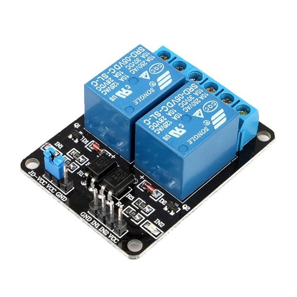
5V 2 Channel Relay Module

  1. The module using Songle relay control.
  2. AC voltage 250V, AC current 10A, maximum DC voltage 30V DC current maximum 10A.
  3. Power indicator (green), Two ways of relay status indicator light (red).
  4. Using 8550 transistor-driven, strong driving ability.
  5. Has the fixed bolt hole and easy installation.

Apple Shopping Event

Hurry and get discounts on all Apple devices up to 20%

65,00 EGP

4 People watching this product now!

Payment Methods:

Description

The 5V 2-Channel Relay Module is an essential component for controlling high-power electrical devices such as motors, lamps, or other home appliances using a low-power microcontroller or logic circuit. The module consists of two relays, which can independently control two devices through digital signals, providing electrical isolation and protection to your microcontroller or control system. It operates at 5V, making it suitable for use with popular microcontrollers like Arduino and Raspberry Pi.

Key Features:

  • 2 Channels: Includes two independent relays, allowing you to control two different devices or circuits simultaneously.
  • 5V Operation: Designed to be powered by a 5V source, which is compatible with most microcontrollers like Arduino, Raspberry Pi, and other development boards.
  • High-Voltage Control: Each relay can switch high-voltage (up to 250V AC or 30V DC) devices, providing isolation between low-voltage control systems and high-voltage circuits.
  • Optocoupler Isolation: Built-in optocouplers for electrical isolation, which protects your microcontroller from high voltages or current spikes in the relays’ controlled devices.
  • LED Indicators: Features LEDs to indicate the status of each relay (ON or OFF), providing clear visual feedback for your circuits.
  • Compact Design: Small, lightweight, and easy to integrate into your breadboard or other circuit designs.
  • Trigger Input: Uses a low-level trigger to activate the relay, meaning the relay is activated when the control pin is LOW (active low configuration).

Specifications:

  • Relay Channels: 2 (independent control of two devices).
  • Operating Voltage: 5V DC.
  • Control Voltage: 5V logic (usually connected to a microcontroller or GPIO pins).
  • Relay Rating:
    • AC: Up to 250V AC, 10A max.
    • DC: Up to 30V DC, 10A max.
  • Current Draw: Typically around 70mA to 100mA per channel when activated.
  • Trigger Method: Active LOW (relay is triggered when the input signal is LOW).
  • Dimensions: Typically around 45mm x 40mm x 20mm, compact and easy to integrate into projects.
  • Protection: Includes flyback diodes to protect the relay coil from voltage spikes when de-energized.

Applications:

  • Home Automation: Control home appliances, lights, fans, or other devices from a microcontroller or smartphone using a relay.
  • Robotics: Can be used in robotics projects to control motors, actuators, or other high-power components.
  • IoT Devices: Used in Internet of Things (IoT) applications for remote control of electrical devices.
  • Automated Systems: Ideal for automating industrial or commercial systems, such as controlling machinery or switching devices in automation systems.
  • Safety Systems: Used in alarm systems to trigger external devices like sirens or lights.

Benefits:

  • Easy to Use: Simple to integrate into projects, requiring only a few connections to control high-voltage devices.
  • Electrical Isolation: Protects your low-voltage circuits and microcontroller from high-voltage spikes, ensuring system stability and safety.
  • Compact and Efficient: Provides a simple solution for switching high-power loads with minimal space requirements.
  • Cost-Effective: An affordable way to add relay control functionality to a wide range of electronic projects.
  • Versatile: Ideal for a wide variety of applications, from hobby projects to industrial systems, due to its ability to control both AC and DC loads.

The 5V 2-Channel Relay Module is an essential tool for anyone working with microcontrollers, automation, or control systems. It provides a safe and easy way to control high-power devices, adding flexibility and functionality to your electronic projects.

🔌
Pin Connections
1 Table
Pin Connections Table 1
BoardSensor PinConnection
RelayIN1-IN22 board digital pins
📟
5V 2 Channel Relay Module
7 Examples • C/C++ | Boards: Arduino Uno, Arduino Nano, Arduino Mega, ESP32, ESP8266, STM32, Raspberry Pi Pico
5V 2 Channel Relay Module - Arduino Uno
5V 2 Channel Relay Module - Arduino Nano
5V 2 Channel Relay Module - Arduino Mega
5V 2 Channel Relay Module - ESP32
5V 2 Channel Relay Module - ESP8266
5V 2 Channel Relay Module - STM32
5V 2 Channel Relay Module - Raspberry Pi Pico
📄 File: 5v_2_channel_relay_module_-_arduino_uno.inoArduino Uno
633 characters
1//ekostra.com
2//electronics store in egypt
3//+201008896258
4
5// Relay IN pins on Arduino Uno: 2, 3. Most cheap relay boards are ACTIVE-LOW (LOW = relay energized) - check yours.
6const int NUM_RELAYS = 2;
7int relayPins[NUM_RELAYS] = {2, 3};
8
9void setup() {
10 for (int i = 0; i < NUM_RELAYS; i++) {
11 pinMode(relayPins[i], OUTPUT);
12 digitalWrite(relayPins[i], HIGH); // start OFF (active-low boards: HIGH = off)
13 }
14}
15
16void loop() {
17 for (int i = 0; i < NUM_RELAYS; i++) {
18 digitalWrite(relayPins[i], LOW); // turn ON
19 delay(500);
20 digitalWrite(relayPins[i], HIGH); // turn OFF
21 delay(200);
22 }
23 delay(1000);
24}
📄 File: 5v_2_channel_relay_module_-_arduino_nano.inoArduino Nano
634 characters
1//ekostra.com
2//electronics store in egypt
3//+201008896258
4
5// Relay IN pins on Arduino Nano: 2, 3. Most cheap relay boards are ACTIVE-LOW (LOW = relay energized) - check yours.
6const int NUM_RELAYS = 2;
7int relayPins[NUM_RELAYS] = {2, 3};
8
9void setup() {
10 for (int i = 0; i < NUM_RELAYS; i++) {
11 pinMode(relayPins[i], OUTPUT);
12 digitalWrite(relayPins[i], HIGH); // start OFF (active-low boards: HIGH = off)
13 }
14}
15
16void loop() {
17 for (int i = 0; i < NUM_RELAYS; i++) {
18 digitalWrite(relayPins[i], LOW); // turn ON
19 delay(500);
20 digitalWrite(relayPins[i], HIGH); // turn OFF
21 delay(200);
22 }
23 delay(1000);
24}
📄 File: 5v_2_channel_relay_module_-_arduino_mega.inoArduino Mega
638 characters
1//ekostra.com
2//electronics store in egypt
3//+201008896258
4
5// Relay IN pins on Arduino Mega: 22, 23. Most cheap relay boards are ACTIVE-LOW (LOW = relay energized) - check yours.
6const int NUM_RELAYS = 2;
7int relayPins[NUM_RELAYS] = {22, 23};
8
9void setup() {
10 for (int i = 0; i < NUM_RELAYS; i++) {
11 pinMode(relayPins[i], OUTPUT);
12 digitalWrite(relayPins[i], HIGH); // start OFF (active-low boards: HIGH = off)
13 }
14}
15
16void loop() {
17 for (int i = 0; i < NUM_RELAYS; i++) {
18 digitalWrite(relayPins[i], LOW); // turn ON
19 delay(500);
20 digitalWrite(relayPins[i], HIGH); // turn OFF
21 delay(200);
22 }
23 delay(1000);
24}
📄 File: 5v_2_channel_relay_module_-_esp32.inoESP32
631 characters
1//ekostra.com
2//electronics store in egypt
3//+201008896258
4
5// Relay IN pins on ESP32: 13, 14. Most cheap relay boards are ACTIVE-LOW (LOW = relay energized) - check yours.
6const int NUM_RELAYS = 2;
7int relayPins[NUM_RELAYS] = {13, 14};
8
9void setup() {
10 for (int i = 0; i < NUM_RELAYS; i++) {
11 pinMode(relayPins[i], OUTPUT);
12 digitalWrite(relayPins[i], HIGH); // start OFF (active-low boards: HIGH = off)
13 }
14}
15
16void loop() {
17 for (int i = 0; i < NUM_RELAYS; i++) {
18 digitalWrite(relayPins[i], LOW); // turn ON
19 delay(500);
20 digitalWrite(relayPins[i], HIGH); // turn OFF
21 delay(200);
22 }
23 delay(1000);
24}
📄 File: 5v_2_channel_relay_module_-_esp8266.inoESP8266
633 characters
1//ekostra.com
2//electronics store in egypt
3//+201008896258
4
5// Relay IN pins on ESP8266: D0, D3. Most cheap relay boards are ACTIVE-LOW (LOW = relay energized) - check yours.
6const int NUM_RELAYS = 2;
7int relayPins[NUM_RELAYS] = {D0, D3};
8
9void setup() {
10 for (int i = 0; i < NUM_RELAYS; i++) {
11 pinMode(relayPins[i], OUTPUT);
12 digitalWrite(relayPins[i], HIGH); // start OFF (active-low boards: HIGH = off)
13 }
14}
15
16void loop() {
17 for (int i = 0; i < NUM_RELAYS; i++) {
18 digitalWrite(relayPins[i], LOW); // turn ON
19 delay(500);
20 digitalWrite(relayPins[i], HIGH); // turn OFF
21 delay(200);
22 }
23 delay(1000);
24}
📄 File: 5v_2_channel_relay_module_-_stm32.inoSTM32
635 characters
1//ekostra.com
2//electronics store in egypt
3//+201008896258
4
5// Relay IN pins on STM32: PA0, PA1. Most cheap relay boards are ACTIVE-LOW (LOW = relay energized) - check yours.
6const int NUM_RELAYS = 2;
7int relayPins[NUM_RELAYS] = {PA0, PA1};
8
9void setup() {
10 for (int i = 0; i < NUM_RELAYS; i++) {
11 pinMode(relayPins[i], OUTPUT);
12 digitalWrite(relayPins[i], HIGH); // start OFF (active-low boards: HIGH = off)
13 }
14}
15
16void loop() {
17 for (int i = 0; i < NUM_RELAYS; i++) {
18 digitalWrite(relayPins[i], LOW); // turn ON
19 delay(500);
20 digitalWrite(relayPins[i], HIGH); // turn OFF
21 delay(200);
22 }
23 delay(1000);
24}
📄 File: 5v_2_channel_relay_module_-_raspberry_pi_pico.inoRaspberry Pi Pico
643 characters
1//ekostra.com
2//electronics store in egypt
3//+201008896258
4
5// Relay IN pins on Raspberry Pi Pico: 10, 11. Most cheap relay boards are ACTIVE-LOW (LOW = relay energized) - check yours.
6const int NUM_RELAYS = 2;
7int relayPins[NUM_RELAYS] = {10, 11};
8
9void setup() {
10 for (int i = 0; i < NUM_RELAYS; i++) {
11 pinMode(relayPins[i], OUTPUT);
12 digitalWrite(relayPins[i], HIGH); // start OFF (active-low boards: HIGH = off)
13 }
14}
15
16void loop() {
17 for (int i = 0; i < NUM_RELAYS; i++) {
18 digitalWrite(relayPins[i], LOW); // turn ON
19 delay(500);
20 digitalWrite(relayPins[i], HIGH); // turn OFF
21 delay(200);
22 }
23 delay(1000);
24}
2-channel relay module.

Specification

Specification

WeightWeight25,0000 g
Dimensions43 × 43 × 17 cm
trigger-current-ma20
switching-voltage-vac250@10A
switching-voltage-vdc30@10A
storage-condition-%e2%84%83– 65 to 125
operating-temperature-c-40 to 85
opt-relative-humidityrh20% ~ 85%

Customer Reviews