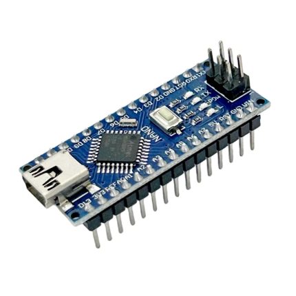
nRF24L01 Wireless Transceiver with Arduino Nano

🔌 ARDUINO TUTORIAL
nRF24L01 Wireless Transceiver with Arduino Nano
Send & receive data wirelessly up to 100m using the 2.4 GHz ISM band.
⚡ 3.3V Logic
🔌 SPI Interface
📶 126 Channels
🔍 Introduction
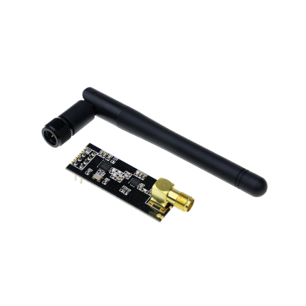
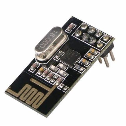
The nRF24L01 is a highly integrated, ultra-low-power (ULP) 2 Mbps RF transceiver IC for the 2.4 GHz ISM band. Designed by Nordic Semiconductor, it is one of the most popular wireless modules in the Arduino community thanks to its low cost, reliability, and impressive range.
💡 Why nRF24L01? Unlike Bluetooth or Wi-Fi modules, it offers a simple SPI interface, no complex pairing overhead, and a standby current below 26µA.
📊 Technical Specifications
Frequency
2.400 – 2.525 GHz
Voltage
1.9V – 3.6V (3.3V typical)
Data Rate
250k / 1M / 2M bps
Interface
4-wire SPI (up to 10 MHz)
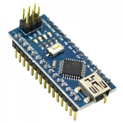
🔌 Wiring Instructions
⚠️ IMPORTANT: The nRF24L01 works with 3.3V logic only. Always power it from the 3.3V pin of the Arduino Nano. It is highly recommended to add a 10µF capacitor between VCC and GND to ensure power stability and reduce noise.
⚡ Connection Summary
💻 Arduino Code Example
📚 Required Library: Install RF24 by TMRh20 via the Arduino Library Manager (version ≥ 1.4.x).
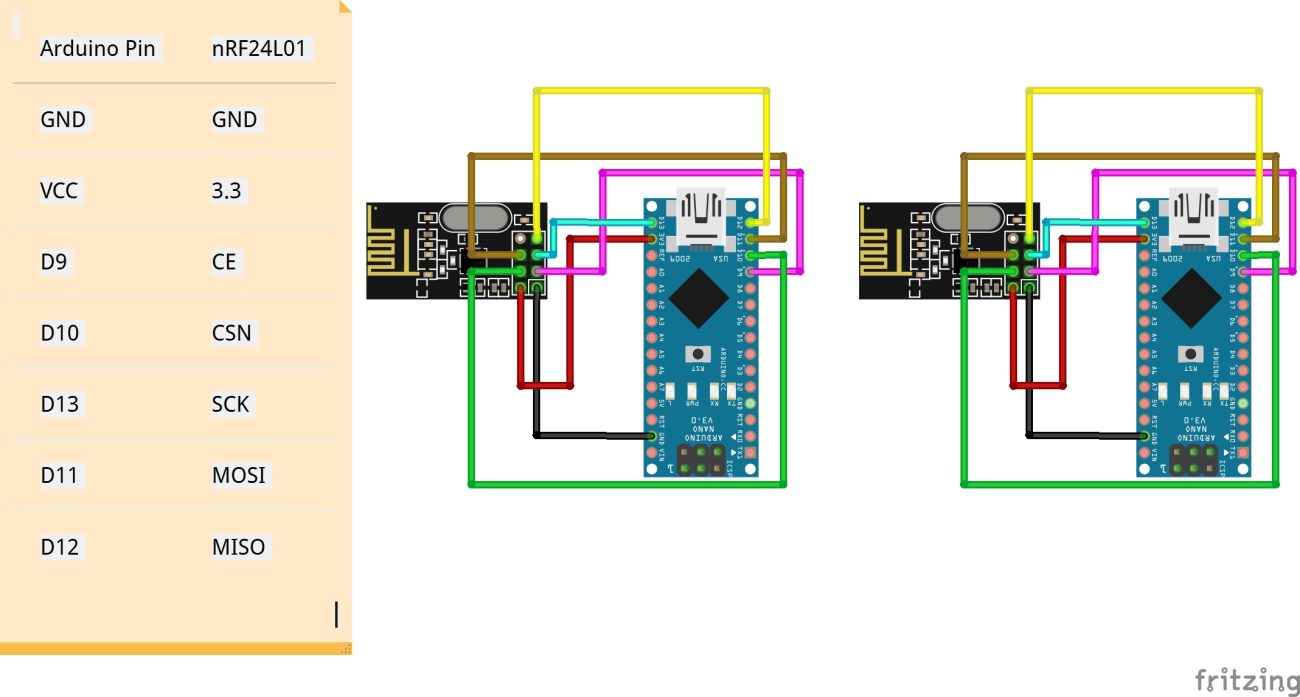
| Arduino Pin | nRF24L01 |
|---|---|
| GND | GND |
| VCC | 3.3 |
| D9 | CE |
| D10 | CSN |
| D13 | SCK |
| D11 | MOSI |
| D12 | MISO |
🚀 Future Applications
The nRF24L01 ecosystem continues to grow. Here are some exciting projects you can build:
Smart Home
Control lights, locks, and appliances wirelessly.
Sensor Networks
Deploy multiple sensor nodes over a large area.
RC Control
Low-latency link for RC cars, drones, and robots.
⚖️ Advantages & Disadvantages
✅ Advantages
- Very low cost – typically under $1 per module.
- Ultra-low power consumption – 900nA in power-down mode.
- High data rate up to 2 Mbps.
- Hardware support for auto-ACK & auto-retransmit.
- 126 selectable channels to avoid RF interference.
- Simple 4-wire SPI interface works seamlessly with any Arduino.
❌ Disadvantages
- 3.3V power only – requires step-down regulation if operating exclusively on a 5V source.
- Highly sensitive to power noise – practically requires a decoupling capacitor.
- Short range on the base model (PCB antenna is ~100m line-of-sight).
- No built-in data encryption standard.
- Half-duplex communication only (TX or RX at one time, not both).
- Build quality varies heavily among cheap clone markets.