Introduction
Are you interested in learning about electronics and want to start with a fun and practical project? Look no further! In this blog post, we will guide you through the process of building your own DIY traffic light circuit. This project is perfect for beginners who want to get their hands dirty with some basic electronics and have a functional end product.
Materials Needed
Step-by-Step Instructions
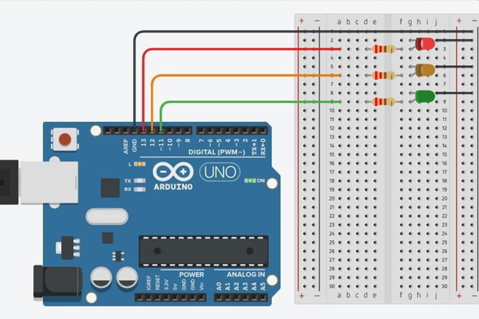
1. Start by setting up your Arduino Uno board on the breadboard. Make sure to connect the power and ground pins correctly.
2. Connect the red LED to pin 13, the yellow LED to pin 12, and the green LED to pin 11 of the Arduino board. Remember to use the 220-ohm resistors in series with each LED to limit the current.
3. Use the jumper wires to connect the other ends of the LEDs to the ground (GND) pin on the Arduino board.
4. Now it’s time to write the code for the traffic light sequence. Open the Arduino IDE and create a new sketch. Start by defining the pin numbers for the LEDs:
int redPin = 13;
int yellowPin = 12;
int greenPin = 11;
5. In the setup function, set the pin modes for the LEDs:
void setup() {
  pinMode(redPin, OUTPUT);
  pinMode(yellowPin, OUTPUT);
  pinMode(greenPin, OUTPUT);
}
6. In the loop function, write the code for the traffic light sequence:
void loop() {
  digitalWrite(redPin, HIGH);
  delay(2000);
  digitalWrite(redPin, LOW);
  digitalWrite(yellowPin, HIGH);
  delay(1000);
  digitalWrite(yellowPin, LOW);
  digitalWrite(greenPin, HIGH);
  delay(2000);
  digitalWrite(greenPin, LOW);
  digitalWrite(yellowPin, HIGH);
  delay(1000);
  digitalWrite(yellowPin, LOW);
}
7. Upload the code to your Arduino board and watch your DIY traffic light circuit come to life!
Conclusion
Building a DIY traffic light circuit is a great way to learn about basic electronics and programming. This project is perfect for beginners and provides a fun and functional end product. So, gather your materials, follow the step-by-step instructions, and enjoy the satisfaction of creating your very own traffic light circuit!


