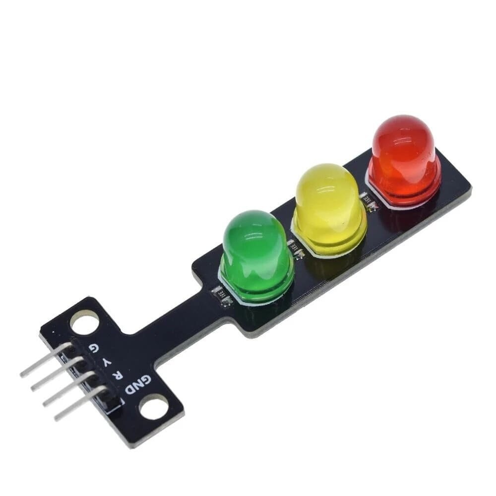
The LED Traffic Lights Signal Module / Digital Signal Output Traffic Light Module is another great interesting DIY accessory by Robu.in. This is a mini-traffic light display module, high brightness, very suitable for the production of a traffic light system model.
Can be connected to the motherboard’s PWM pin to control the brightness of the light.
Package Includes : 1 x LED traffic lights signal module.
Pin Connections Table 1
Board Sensor Pin Connection Traffic Light R/Y/G 3 board digital pins
LED Traffic Lights Signal Module / Digital Signal Output Traffic Light Module - Arduino Uno
LED Traffic Lights Signal Module / Digital Signal Output Traffic Light Module - Arduino Nano
LED Traffic Lights Signal Module / Digital Signal Output Traffic Light Module - Arduino Mega
LED Traffic Lights Signal Module / Digital Signal Output Traffic Light Module - ESP32
LED Traffic Lights Signal Module / Digital Signal Output Traffic Light Module - ESP8266
LED Traffic Lights Signal Module / Digital Signal Output Traffic Light Module - STM32
LED Traffic Lights Signal Module / Digital Signal Output Traffic Light Module - Raspberry Pi Pico
1 //ekostra.com
2 //electronics store in egypt
3 //+201008896258
4
5 // Red=2 , Yellow=3 , Green=4 on Arduino Uno
6 #define RED_PIN 2
7 #define YELLOW_PIN 3
8 #define GREEN_PIN 4
9
10 void setup () {
11 pinMode (RED_PIN, OUTPUT );
12 pinMode (YELLOW_PIN, OUTPUT );
13 pinMode (GREEN_PIN, OUTPUT );
14 }
15
16 void loop () {
17 digitalWrite (GREEN_PIN, HIGH ); delay (3000 ); digitalWrite (GREEN_PIN, LOW );
18 digitalWrite (YELLOW_PIN, HIGH ); delay (1000 ); digitalWrite (YELLOW_PIN, LOW );
19 digitalWrite (RED_PIN, HIGH ); delay (3000 ); digitalWrite (RED_PIN, LOW );
20 }
1 //ekostra.com
2 //electronics store in egypt
3 //+201008896258
4
5 // Red=2 , Yellow=3 , Green=4 on Arduino Nano
6 #define RED_PIN 2
7 #define YELLOW_PIN 3
8 #define GREEN_PIN 4
9
10 void setup () {
11 pinMode (RED_PIN, OUTPUT );
12 pinMode (YELLOW_PIN, OUTPUT );
13 pinMode (GREEN_PIN, OUTPUT );
14 }
15
16 void loop () {
17 digitalWrite (GREEN_PIN, HIGH ); delay (3000 ); digitalWrite (GREEN_PIN, LOW );
18 digitalWrite (YELLOW_PIN, HIGH ); delay (1000 ); digitalWrite (YELLOW_PIN, LOW );
19 digitalWrite (RED_PIN, HIGH ); delay (3000 ); digitalWrite (RED_PIN, LOW );
20 }
1 //ekostra.com
2 //electronics store in egypt
3 //+201008896258
4
5 // Red=2 , Yellow=3 , Green=4 on Arduino Mega
6 #define RED_PIN 2
7 #define YELLOW_PIN 3
8 #define GREEN_PIN 4
9
10 void setup () {
11 pinMode (RED_PIN, OUTPUT );
12 pinMode (YELLOW_PIN, OUTPUT );
13 pinMode (GREEN_PIN, OUTPUT );
14 }
15
16 void loop () {
17 digitalWrite (GREEN_PIN, HIGH ); delay (3000 ); digitalWrite (GREEN_PIN, LOW );
18 digitalWrite (YELLOW_PIN, HIGH ); delay (1000 ); digitalWrite (YELLOW_PIN, LOW );
19 digitalWrite (RED_PIN, HIGH ); delay (3000 ); digitalWrite (RED_PIN, LOW );
20 }
1 //ekostra.com
2 //electronics store in egypt
3 //+201008896258
4
5 // Red=25 , Yellow=26 , Green=27 on ESP32
6 #define RED_PIN 25
7 #define YELLOW_PIN 26
8 #define GREEN_PIN 27
9
10 void setup () {
11 pinMode (RED_PIN, OUTPUT );
12 pinMode (YELLOW_PIN, OUTPUT );
13 pinMode (GREEN_PIN, OUTPUT );
14 }
15
16 void loop () {
17 digitalWrite (GREEN_PIN, HIGH ); delay (3000 ); digitalWrite (GREEN_PIN, LOW );
18 digitalWrite (YELLOW_PIN, HIGH ); delay (1000 ); digitalWrite (YELLOW_PIN, LOW );
19 digitalWrite (RED_PIN, HIGH ); delay (3000 ); digitalWrite (RED_PIN, LOW );
20 }
1 //ekostra.com
2 //electronics store in egypt
3 //+201008896258
4
5 // Red=D5, Yellow=D6, Green=D7 on ESP8266
6 #define RED_PIN D5
7 #define YELLOW_PIN D6
8 #define GREEN_PIN D7
9
10 void setup () {
11 pinMode (RED_PIN, OUTPUT );
12 pinMode (YELLOW_PIN, OUTPUT );
13 pinMode (GREEN_PIN, OUTPUT );
14 }
15
16 void loop () {
17 digitalWrite (GREEN_PIN, HIGH ); delay (3000 ); digitalWrite (GREEN_PIN, LOW );
18 digitalWrite (YELLOW_PIN, HIGH ); delay (1000 ); digitalWrite (YELLOW_PIN, LOW );
19 digitalWrite (RED_PIN, HIGH ); delay (3000 ); digitalWrite (RED_PIN, LOW );
20 }
1 //ekostra.com
2 //electronics store in egypt
3 //+201008896258
4
5 // Red=PA0, Yellow=PA1, Green=PA2 on STM32
6 #define RED_PIN PA0
7 #define YELLOW_PIN PA1
8 #define GREEN_PIN PA2
9
10 void setup () {
11 pinMode (RED_PIN, OUTPUT );
12 pinMode (YELLOW_PIN, OUTPUT );
13 pinMode (GREEN_PIN, OUTPUT );
14 }
15
16 void loop () {
17 digitalWrite (GREEN_PIN, HIGH ); delay (3000 ); digitalWrite (GREEN_PIN, LOW );
18 digitalWrite (YELLOW_PIN, HIGH ); delay (1000 ); digitalWrite (YELLOW_PIN, LOW );
19 digitalWrite (RED_PIN, HIGH ); delay (3000 ); digitalWrite (RED_PIN, LOW );
20 }
1 //ekostra.com
2 //electronics store in egypt
3 //+201008896258
4
5 // Red=10 , Yellow=11 , Green=12 on Raspberry Pi Pico
6 #define RED_PIN 10
7 #define YELLOW_PIN 11
8 #define GREEN_PIN 12
9
10 void setup () {
11 pinMode (RED_PIN, OUTPUT );
12 pinMode (YELLOW_PIN, OUTPUT );
13 pinMode (GREEN_PIN, OUTPUT );
14 }
15
16 void loop () {
17 digitalWrite (GREEN_PIN, HIGH ); delay (3000 ); digitalWrite (GREEN_PIN, LOW );
18 digitalWrite (YELLOW_PIN, HIGH ); delay (1000 ); digitalWrite (YELLOW_PIN, LOW );
19 digitalWrite (RED_PIN, HIGH ); delay (3000 ); digitalWrite (RED_PIN, LOW );
20 }
Project Notes: Three LEDs (red/yellow/green) on one small board - simple digitalWrite sequencing.




 Specification


