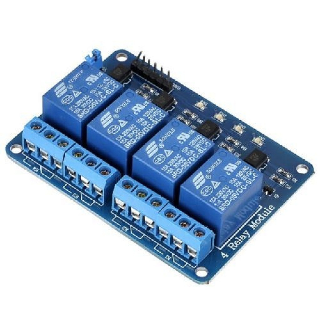
This is a 5V 4-Channel Relay interface board, be able to control various appliances and other equipment with large current. It can be controlled directly by Microcontroller (for Arduino, 8051, AVR, PIC, DSP, ARM, ARM, MSP430, TTL logic).
Features:
5V 4-Channel Relay interface board and each one needs 15-20mA Driver Current.
Equipped with high-current relay, AC250V 10A; DC30V 10A.
Standard interface that can be controlled directly by microcontroller (for Arduino, 8051, AVR, PIC, DSP, ARM, ARM, MSP430, TTL logic).
Indication LED’s for Relay output status.
Package Includes: 1 x 5V 4 Channel Relay Module.
Pin Connections Table 1
Board Sensor Pin Connection Relay IN1-IN4 4 board digital pins
5V 4 Channel Relay Module - Arduino Uno
5V 4 Channel Relay Module - Arduino Nano
5V 4 Channel Relay Module - Arduino Mega
5V 4 Channel Relay Module - ESP32
5V 4 Channel Relay Module - ESP8266
5V 4 Channel Relay Module - STM32
5V 4 Channel Relay Module - Raspberry Pi Pico
1 //ekostra.com
2 //electronics store in egypt
3 //+201008896258
4
5 // Relay IN pins on Arduino Uno: 2 , 3 , 4 , 5 . Most cheap relay boards are ACTIVE-LOW (LOW = relay energized) - check yours.
6 const int NUM_RELAYS = 4 ;
7 int relayPins[NUM_RELAYS] = {2 , 3 , 4 , 5 };
8
9 void setup () {
10 for (int i = 0 ; i < NUM_RELAYS; i++) {
11 pinMode (relayPins[i], OUTPUT );
12 digitalWrite (relayPins[i], HIGH ); // start OFF (active-low boards: HIGH = off)
13 }
14 }
15
16 void loop () {
17 for (int i = 0 ; i < NUM_RELAYS; i++) {
18 digitalWrite (relayPins[i], LOW ); // turn ON
19 delay (500 );
20 digitalWrite (relayPins[i], HIGH ); // turn OFF
21 delay (200 );
22 }
23 delay (1000 );
24 }
1 //ekostra.com
2 //electronics store in egypt
3 //+201008896258
4
5 // Relay IN pins on Arduino Nano: 2 , 3 , 4 , 5 . Most cheap relay boards are ACTIVE-LOW (LOW = relay energized) - check yours.
6 const int NUM_RELAYS = 4 ;
7 int relayPins[NUM_RELAYS] = {2 , 3 , 4 , 5 };
8
9 void setup () {
10 for (int i = 0 ; i < NUM_RELAYS; i++) {
11 pinMode (relayPins[i], OUTPUT );
12 digitalWrite (relayPins[i], HIGH ); // start OFF (active-low boards: HIGH = off)
13 }
14 }
15
16 void loop () {
17 for (int i = 0 ; i < NUM_RELAYS; i++) {
18 digitalWrite (relayPins[i], LOW ); // turn ON
19 delay (500 );
20 digitalWrite (relayPins[i], HIGH ); // turn OFF
21 delay (200 );
22 }
23 delay (1000 );
24 }
1 //ekostra.com
2 //electronics store in egypt
3 //+201008896258
4
5 // Relay IN pins on Arduino Mega: 22 , 23 , 24 , 25 . Most cheap relay boards are ACTIVE-LOW (LOW = relay energized) - check yours.
6 const int NUM_RELAYS = 4 ;
7 int relayPins[NUM_RELAYS] = {22 , 23 , 24 , 25 };
8
9 void setup () {
10 for (int i = 0 ; i < NUM_RELAYS; i++) {
11 pinMode (relayPins[i], OUTPUT );
12 digitalWrite (relayPins[i], HIGH ); // start OFF (active-low boards: HIGH = off)
13 }
14 }
15
16 void loop () {
17 for (int i = 0 ; i < NUM_RELAYS; i++) {
18 digitalWrite (relayPins[i], LOW ); // turn ON
19 delay (500 );
20 digitalWrite (relayPins[i], HIGH ); // turn OFF
21 delay (200 );
22 }
23 delay (1000 );
24 }
1 //ekostra.com
2 //electronics store in egypt
3 //+201008896258
4
5 // Relay IN pins on ESP32: 13 , 14 , 27 , 26 . Most cheap relay boards are ACTIVE-LOW (LOW = relay energized) - check yours.
6 const int NUM_RELAYS = 4 ;
7 int relayPins[NUM_RELAYS] = {13 , 14 , 27 , 26 };
8
9 void setup () {
10 for (int i = 0 ; i < NUM_RELAYS; i++) {
11 pinMode (relayPins[i], OUTPUT );
12 digitalWrite (relayPins[i], HIGH ); // start OFF (active-low boards: HIGH = off)
13 }
14 }
15
16 void loop () {
17 for (int i = 0 ; i < NUM_RELAYS; i++) {
18 digitalWrite (relayPins[i], LOW ); // turn ON
19 delay (500 );
20 digitalWrite (relayPins[i], HIGH ); // turn OFF
21 delay (200 );
22 }
23 delay (1000 );
24 }
1 //ekostra.com
2 //electronics store in egypt
3 //+201008896258
4
5 // Relay IN pins on ESP8266: D0, D3, D4, D5. Most cheap relay boards are ACTIVE-LOW (LOW = relay energized) - check yours.
6 const int NUM_RELAYS = 4 ;
7 int relayPins[NUM_RELAYS] = {D0, D3, D4, D5};
8
9 void setup () {
10 for (int i = 0 ; i < NUM_RELAYS; i++) {
11 pinMode (relayPins[i], OUTPUT );
12 digitalWrite (relayPins[i], HIGH ); // start OFF (active-low boards: HIGH = off)
13 }
14 }
15
16 void loop () {
17 for (int i = 0 ; i < NUM_RELAYS; i++) {
18 digitalWrite (relayPins[i], LOW ); // turn ON
19 delay (500 );
20 digitalWrite (relayPins[i], HIGH ); // turn OFF
21 delay (200 );
22 }
23 delay (1000 );
24 }
1 //ekostra.com
2 //electronics store in egypt
3 //+201008896258
4
5 // Relay IN pins on STM32: PA0, PA1, PA2, PA3. Most cheap relay boards are ACTIVE-LOW (LOW = relay energized) - check yours.
6 const int NUM_RELAYS = 4 ;
7 int relayPins[NUM_RELAYS] = {PA0, PA1, PA2, PA3};
8
9 void setup () {
10 for (int i = 0 ; i < NUM_RELAYS; i++) {
11 pinMode (relayPins[i], OUTPUT );
12 digitalWrite (relayPins[i], HIGH ); // start OFF (active-low boards: HIGH = off)
13 }
14 }
15
16 void loop () {
17 for (int i = 0 ; i < NUM_RELAYS; i++) {
18 digitalWrite (relayPins[i], LOW ); // turn ON
19 delay (500 );
20 digitalWrite (relayPins[i], HIGH ); // turn OFF
21 delay (200 );
22 }
23 delay (1000 );
24 }
1 //ekostra.com
2 //electronics store in egypt
3 //+201008896258
4
5 // Relay IN pins on Raspberry Pi Pico: 10 , 11 , 12 , 13 . Most cheap relay boards are ACTIVE-LOW (LOW = relay energized) - check yours.
6 const int NUM_RELAYS = 4 ;
7 int relayPins[NUM_RELAYS] = {10 , 11 , 12 , 13 };
8
9 void setup () {
10 for (int i = 0 ; i < NUM_RELAYS; i++) {
11 pinMode (relayPins[i], OUTPUT );
12 digitalWrite (relayPins[i], HIGH ); // start OFF (active-low boards: HIGH = off)
13 }
14 }
15
16 void loop () {
17 for (int i = 0 ; i < NUM_RELAYS; i++) {
18 digitalWrite (relayPins[i], LOW ); // turn ON
19 delay (500 );
20 digitalWrite (relayPins[i], HIGH ); // turn OFF
21 delay (200 );
22 }
23 delay (1000 );
24 }
Project Notes: 4-channel relay module.





 Specification


