L298N Motor Driver Module – 2A Dual Channel
🔌 ARDUINO TUTORIAL
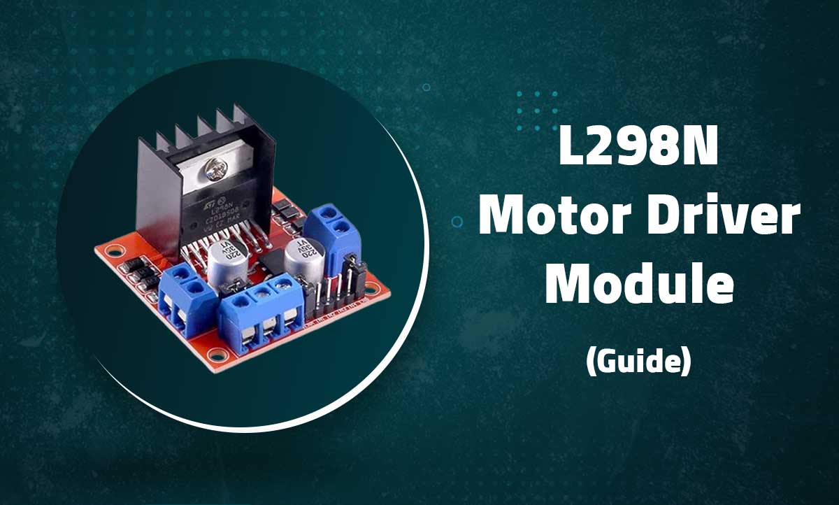
L298N Motor Driver Module for DC & Stepper Motors
2A Dual Channel H-Bridge for bidirectionally controlling inductive loads.
🔄 Bidirectional
🔌 5V-35V Range
📶 PWM Control
🔍 Introduction
The L298N is a high-voltage, high-current dual full-bridge driver designed to control inductive loads like DC motors and stepper motors. This module can drive two DC motors bidirectionally or one stepper motor with up to 2A continuous current per channel.
💡 Why L298N? Unlike using single transistors, it provides a full H-bridge setup for easy bidirectional control, handles high current loads, and allows for precise speed control via PWM logic.
📊 Technical Specifications
Voltage
5V – 35V DC
Current
2A per channel (3A Peak)
Driver IC
L298N Dual H-Bridge
Control
PWM & Direction
🔌 Wiring Instructions
⚠️ IMPORTANT: Keep the jumper on the +5V terminal ONLY if your supply is 12V or less and you want to use the onboard regulator. Remove the jumper if supplying more than 12V to avoid damaging the regulator.
⚡ Connection Summary
| Terminal | Function | Connection |
|---|---|---|
| +12V | Motor Power (5-35V) | Battery positive |
| GND | Ground | Battery negative |
| +5V | Logic Power | 5V (if jumper removed) |
| ENA / ENB | Channel A/B Enable | PWM capable pins (e.g., D9/D10) |
| IN1 / IN2 | Channel A Control | Digital pins (e.g., D8/D7) |
| IN3 / IN4 | Channel B Control | Digital pins (e.g., D6/D5) |
| OUT1/2 & OUT3/4 | Motor A & B | Motor Terminals |
💻 Arduino Code Examples
📚 Required Library: No special library is required for basic DC motor control. For Stepper motors, the AccelStepper library is highly recommended for better performance.
| Arduino Pin | L298n Driver motor module |
|---|---|
| GND | GND |
| -- | 12V VCC External power supplay |
| D10 | inA |
| D9 | in1 |
| D8 | in2 |
| D5 | inB |
| D6 | in3 |
| D7 | in4 |
🚀 Project Ideas
The L298N is highly versatile. Here are some exciting projects you can build:
Robot Platform
Differential drive mobile robot for obstacle avoidance.
CNC Controller
Stepper motor control for DIY CNC machines.
Camera Slider
Smooth motorized motion control for videography.
⚖️ Advantages & Disadvantages
✅ Advantages
- High Power Capacity – 2A continuous current per channel.
- Bidirectional Control – Full forward and reverse control of two DC motors.
- Wide Operating Range – Operates smoothly from 5V to 35V DC.
- Speed Control – Hardware support for PWM speed modulation.
- Built-in Regulator – Can power 5V logic systems when the source is under 12V.
❌ Disadvantages
- Voltage Drop – BJT architecture causes a ~1.5V-2V drop delivered to the motors.
- Heat Generation – Highly inefficient compared to modern drivers, practically requiring the bulky heatsink.
- Older Technology – Superseded by more efficient MOSFET drivers (like TB6612FNG) for low-power builds.
- Bulky Footprint – Takes up considerable space in tight enclosures.
🔧 Troubleshooting
- Motor Not Moving: Check if enable jumpers are securely in place (if you are not using PWM pins). Verify the motor power supply provides adequate voltage/current and test with a direct battery connection.
- Overheating: Ensure the heatsink is properly attached. Reduce the current draw (by using smaller motors) or add a cooling fan if you are driving near the 2A continuous limit.
- Erratic Behavior: Add a 100μF ceramic capacitor across your motor terminals to reduce electrical noise. Always ensure your logic and motor power supplies share a common ground (GND).