PIC16F877A-I/P
-
8-bit Microchip PIC microcontroller with 14 KB Flash
-
368 Bytes RAM and 256 Bytes EEPROM
-
10-bit 8-channel ADC
-
USART, SPI, I2C communication interfaces
-
Up to 20 MHz clock speed
-
40-pin PDIP package suitable for prototyping
220,00 EGP
In stock
In stock
Payment Methods:
Description
- High-Performance RISC CPU
- – Only 35 single word instructions to learn
- – All instructions are single cycle (1µs) except for program branches
- – Operating speed: DC – 20MHz clock input
- – 8 kBytes Flash Program Memory
- – 368 Byte RAM Data Memory
- – 256 Byte EEPROM Data Memory
- – In-circuit Serial Programming
- – Interrupt Capability (up to 10 sources)
- Peripheral Features
- – Two 8-bit timer/counter(TMR0, TMR2) with 8-bit programmable prescalar
- – One 16 bit timer/counter (TMR1)
- – High current source/sink for direct LED drive
- – Watchdog Timer (WDT) with Separate RC Oscillator
- – Two Capture, Compare, PWM Modules
- – Synchronous Serial Port with SPI and I²C
- – Eight Channel, 10-bit Analog to Digital Converter
- – Universal Synchronous Asynchronous Receiver Transmitter (USART)
- Special Microcontroller Features
- – Power-On Reset
- – Power-up Timer (PWRT) and Oscillator Start-Up Timer (OST)
- – 1,000 erase/write cycles Enhanced Flash Program Memory
- – 1,000,000 typical erase/write cycles EEPROM Data Memory
- – Selectable Oscillator Options
- CMOS Technology
- – Low power, high speed CMOS FLASH technology
- – Fully Static Design
- – Low Power Consumption
- I/O and Packages
- – 33 I/O pins with individual direction control
- – 40-pin DIP
IC16F877A-I/P – MICROCHIP
Note:
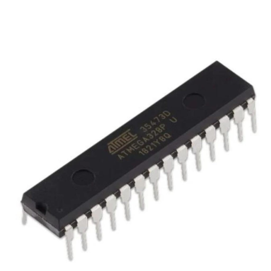
- Product Images are shown for illustrative purposes only and may differ from the actual product.
- For Technical Specifications about the IC go through the Datasheet in the Attachment section.
Package Includes:
1 x PIC16F877A-I/P – MICROCHIP
Specification
General
| Weight Weight | 0,0000 g |
|---|---|
| number-of-i-o-pins |
33 |
| product-type |
High-Performance RISC CPU |
| operating-frequency |
DC – 20MHz |
| instruction-set |
35 single-word instructions |
| flash-program-memory |
8 kBytes |
| ram-data-memory |
368 Bytes |
| eeprom-data-memory |
256 Bytes |
| programming |
In-circuit Serial Programming |
| interrupts |
Up to 10 interrupt sources |
| timers-counters |
Two 8-bit timers/counters (TMR0, TMR2) with 8-bit programmable prescaler |
| additional-features |
High current source/sink for direct LED drive |


