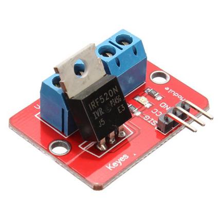

IRF520 MOSFET DRIVER MODULE
60,00 EGP
Payment Methods:
Description
The IRF520 MOSFET Driver Module is an essential break-out board designed to bridge low-power microcontrollers with high-power DC peripherals. Perfect for DIY electronics, robotics, and automation setups, this module allows devices like an Arduino, Raspberry Pi, or ESP32 to safely control high-current loads that exceed their native GPIO pin limitations.
Equipped with a robust IRF520N Power MOSFET, the board utilizes a pulse-width modulation (PWM) or standard digital signal to smoothly control DC motors, high-power LED strips, solenoid valves, or miniature heating elements. The module features an onboard status LED to give immediate visual feedback of the output state, and heavy-duty screw terminals to ensure secure, low-resistance wiring connections.
Technical Specifications
Electrical Parameters
| Attribute | Specification |
| Control / Trigger Voltage (VCC) | 3.3V – 5V DC (Compatible with microcontrollers) |
| Output Load Voltage (VIN) | 0V – 24V DC |
| Continuous Output Current | Up to 1A (Without external heatsink) |
| Peak Output Current | Up to 5A (Requires an external heatsink & proper thermal management) |
| Maximum Load Power | ~60W (With adequate cooling) |
| Signal Input Type | Digital High/Low or PWM (Pulse Width Modulation) |
Pinout & Interface Configurations
Control Side (3-Pin Male Header):
-
SIG (Signal): Input trigger pin connected to the microcontroller’s GPIO/PWM output pin.
-
VCC: Power input for the onboard circuitry (typically 5V or 3.3V matching logic level).
-
GND: Common ground connection shared with the microcontroller.
Load Side (Screw Terminals):
-
VIN / GND (Terminal 1): Connects to the external power supply for the high-power load (0V to 24V).
-
V+ / V- (Terminal 2): Connects directly to the target DC peripheral (e.g., motor, LED strip).
Core Product Features
-
PWM Speed & Dimming Control: Seamlessly handles PWM signal streams, enabling precise speed control for DC motors or smooth brightness dimming for LED strings.
-
Microcontroller Protection: Acts as an electrical buffer, isolating your sensitive development board’s logic lines from high-voltage supply noises.
-
Onboard State LED Indicator: Includes a miniature surface-mount LED that illuminates when the control signal is high, streamlining rapid circuit debugging and validation.
-
Compact, Mountable Footprint: Features dual mechanical M3 mounting holes for solid fastening into custom control boxes or 3D-printed project enclosures.
Technical Note: For logic level inputs of 3.3V (e.g., ESP32 or Raspberry Pi Pico), the maximum output current will be significantly lower because the IRF520 is not a logic-level MOSFET and requires closer to 5V at the gate to fully open the channel. If driving loads above 1A, an external heatsink is strictly required.
Specification
General
| WeightWeight | 0,0000 g |
|---|