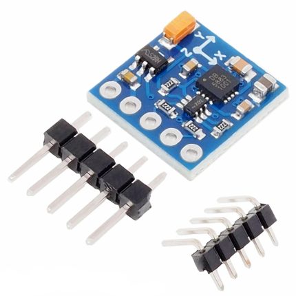

GY-271 HMC5883L Triple Axis Magnetometer Sensor Module
- 3-axis magnetic electronic compass.
- Precise heading information.
- Operating Voltage: 3 -5 V DC.
- Driver Chip: HMC5883L.
- Communication: I2C protocol.
- Measuring range: ± 1.3-8 Gauss.
150,00 EGP
In stock
In stock
Payment Methods:
Description
The GY-271 HMC5883L Triple-Axis Magnetometer Sensor Module is a popular sensor used to measure the magnetic field in three dimensions (X, Y, and Z axes). It uses the HMC5883L magnetometer IC, which is designed for accurate and low-power magnetic field sensing, and is widely used in various applications like electronic compasses, robotics, and other systems where orientation and navigation are important.
Key Features of GY-271 HMC5883L Module:
-
Triple-Axis Magnetic Field Measurement:
- The sensor can measure the magnetic field along the X, Y, and Z axes, making it ideal for detecting the orientation and direction of the sensor relative to Earth’s magnetic field.
-
Range of ±1.3 to ±8 Gauss:
- The HMC5883L has a configurable sensitivity range of ±1.3 Gauss to ±8 Gauss, which determines how sensitive the sensor is to the Earth’s magnetic field. The default range is typically set to ±1.3 Gauss for most applications, providing good resolution for compass or heading applications.
-
Digital Output (I2C Interface):
- The HMC5883L communicates with a microcontroller (like Arduino) using the I2C protocol. This makes it easy to connect and interact with microcontrollers, as only two wires (SCL and SDA) are needed for communication, in addition to power and ground.
-
Low Power Consumption:
- The module operates with low power, making it suitable for battery-powered applications. It’s typically used in systems where power consumption is a concern, such as portable devices and mobile robotics.
-
Integrated Temperature Compensation:
- The HMC5883L includes built-in temperature compensation to reduce temperature-induced errors in the magnetometer readings.
-
Small Form Factor:
- The GY-271 module is small and easy to integrate into various projects. Its compact size makes it ideal for portable devices and systems with limited space.
-
Onboard Voltage Regulator:
- The GY-271 module typically includes an onboard voltage regulator, so it can be powered by a range of voltages (usually 3.3V to 5V).
-
Pre-calibrated Output:
- The module comes with pre-calibrated data output, making it easier for users to obtain readings without needing to perform complex calibration procedures.
Pinout of GY-271 HMC5883L Module:
The GY-271 HMC5883L module typically has the following pins:
| Pin | Name | Description |
|---|---|---|
| VCC | Power | 3.3V to 5V input power. |
| GND | Ground | Ground connection. |
| SCL | Serial Clock Line (I2C) | Clock signal for I2C communication. |
| SDA | Serial Data Line (I2C) | Data signal for I2C communication. |
| DRDY | Data Ready (optional) | Output pin to indicate that new data is available (optional). |
| ADDR | I2C Address Select | Used to set the I2C address (typically either 0x1E or 0x1D). |
Connecting the GY-271 HMC5883L to Arduino:
To connect the GY-271 HMC5883L to an Arduino (e.g., Arduino Uno), you need to connect the SCL and SDA pins of the module to the corresponding I2C pins on the Arduino. Here’s how you can wire it:
- VCC (GY-271) → 5V (Arduino)
- GND (GY-271) → GND (Arduino)
- SCL (GY-271) → A5 (Arduino Uno) (SCL Pin)
- SDA (GY-271) → A4 (Arduino Uno) (SDA Pin)
Note: The wiring may be different if you’re using a different Arduino model (like Arduino Mega), as the I2C pins may be different.
Example Arduino Code to Read Data from the GY-271 HMC5883L Module:
You can use the Wire library in the Arduino IDE for I2C communication, along with an additional library like “Adafruit_HMC5883_U” (available in the Arduino library manager) to easily communicate with the sensor and get readings.
Here’s an example of how you can read the magnetic field values in all three axes (X, Y, and Z):
-
Install the Adafruit HMC5883L Library:
- Go to Sketch > Include Library > Manage Libraries.
- In the library manager, search for “Adafruit HMC5883L” and install the library.
-
Example Code:
Explanation of the Code:
- Adafruit_HMC5883_U.h: This is the header file for the Adafruit HMC5883L library, which simplifies interacting with the sensor.
- mag.begin(): Initializes the magnetometer sensor.
- mag.getEvent(): Reads the magnetic field strength in three axes (X, Y, Z) and stores the result in an
eventstructure. - Serial.print(): Outputs the readings from the X, Y, and Z axes to the serial monitor.
- MODE_CONTINUOUS: The sensor is set to continuously output data.
Applications of GY-271 HMC5883L:
-
Electronic Compass:
- Used in navigation systems and GPS units to provide orientation relative to Earth’s magnetic field.
-
Robotics:
- Used in robots for heading, orientation, and navigation, especially in autonomous or mobile robots.
-
Geophysical Research:
- Can be used to measure and monitor the magnetic field of the Earth or other objects in scientific studies.
-
Augmented Reality (AR):
- Helps determine the orientation of AR devices relative to magnetic North, improving accuracy in AR applications.
-
Smartphones and Wearable Devices:
- Integrated in mobile devices to provide compass functionalities.
-
Magnetic Field Detection:
- Used in industrial applications for detecting magnetic fields and anomalies.
Tips:
- Calibration: The HMC5883L magnetometer requires calibration for accurate heading and orientation readings. To get accurate compass heading, you’ll need to calibrate the sensor by moving it in all directions to map the Earth’s magnetic field.
- Interference: The sensor can be affected by local magnetic fields such as from motors, wires, or metal objects. It’s important to avoid placing the sensor near such sources of interference for best accuracy.
- Power Supply: If you’re using the module in a battery-powered project, ensure that your power supply is stable and meets the voltage requirements (typically 3.3V to 5V).
Specification
General
| WeightWeight | 0,0000 g |
|---|---|
 Dimensions Dimensions | 2 × 1,5 × 0,5 cm |
| Product Name | GY-271 HMC5883L Triple Axis Magnetometer Sensor Module |
| Type | Magnetometer / Compass Sensor |
| Model | HMC5883L |
| Axes | 3 (X, Y, Z) |
| Interface | I2C (SDA, SCL) |
| Supply Voltage | 3.3V – 5V DC |
| Measurement Range | ±8 Gauss |
| Resolution | 5 mG (typical) |
| Data Rate | 0.75 Hz – 75 Hz |
| Operating Temperature Range | -40°C – +85°C |
| Mounting Type | PCB Module / Breadboard Compatible |
| Material | FR-4 PCB with SMD Components |
| Applications | Compass Module, Navigation, Robotics, Arduino / DIY Projects |
| Package Contents | 1× GY-271 HMC5883L Triple Axis Magnetometer Sensor Module |
Customer Reviews
Related Products