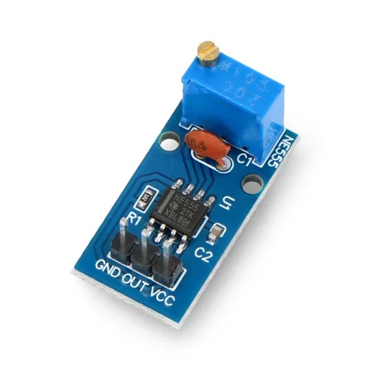
NE555 is a Pulse Frequency Duty Cycle Adjustable Module Square Wave Signal Generator. The output frequency range is selectable. Duty cycle and frequency is not separately adjustable, adjusting the duty cycle will change the frequency. Single channel signal output, the output square wave duty ratio is about fifty percent.
The general use of module generates pulses from approximately 4Hz to 1.3Khz. Utilizes the popular NE555 timer IC operating as an astable multivibrator. The module has ten-turn frequency adjustment control and power on LED. Use for stepper motor pulses, testers etc.
The 555 timer IC is an integrated circuit (chip) used in a variety of timer, pulse generation, and oscillator applications. The 555 can be used to provide time delays, as an oscillator, and as a flip-flop element. Derivatives provide up to four timing circuits in one package. Introduced in 1971 by Signetics, the 555 is still in widespread use due to its ease of use, low price, and stability. It is now made by many companies in the original bipolar and also in low-power CMOS types.
This module can be used as a square-wave signal generator. It generates square wave signals used for experimental development. It also generates square wave signal driving motor drive. With adjustable pulses generated for use by the MCU and adjustable pulse control related circuits.
Features:
Color: Blue
Working voltage: 5-12V
Minimum – 50% duty cycle, 3.7 Hz & Maximum – 98% duty cycle, 1.3KHz
100% Brand new and high quality!
A single channel output, the output duty cycle square wave is about fifty percent.
Onboard adjustable resistance, resistance can be controlled to adjust the output frequency.
Best choice for yourself or your friend. You will not be disappointed!
Package Includes:
1 x Frequency Adjustable Pulse Generator Module NE555
Pin Connections Table 1
Board Sensor Pin Connection NE555 Module OUT board digital pin
Frequency Adjustable Pulse Generator Module NE555 - Arduino Uno
Frequency Adjustable Pulse Generator Module NE555 - Arduino Nano
Frequency Adjustable Pulse Generator Module NE555 - Arduino Mega
Frequency Adjustable Pulse Generator Module NE555 - ESP32
Frequency Adjustable Pulse Generator Module NE555 - ESP8266
Frequency Adjustable Pulse Generator Module NE555 - STM32
Frequency Adjustable Pulse Generator Module NE555 - Raspberry Pi Pico
1 //ekostra.com
2 //electronics store in egypt
3 //+201008896258
4
5 // OUT pin 2 on Arduino Uno (module's own R/C network sets the base frequency in hardware; the adjustable pot on the board changes it further)
6 #define SIGNAL_PIN 2
7
8 void setup () {
9 Serial.begin (115200 );
10 pinMode (SIGNAL_PIN, INPUT );
11 }
12
13 void loop () {
14 unsigned long period = pulseIn (SIGNAL_PIN, HIGH ) + pulseIn (SIGNAL_PIN, LOW );
15 if (period > 0 ) {
16 float freq = 1000000.0 / period;
17 Serial.print ("Frequency: "); Serial.print (freq); Serial.println (" Hz");
18 }
19 delay (200 );
20 }
1 //ekostra.com
2 //electronics store in egypt
3 //+201008896258
4
5 // OUT pin 2 on Arduino Nano (module's own R/C network sets the base frequency in hardware; the adjustable pot on the board changes it further)
6 #define SIGNAL_PIN 2
7
8 void setup () {
9 Serial.begin (115200 );
10 pinMode (SIGNAL_PIN, INPUT );
11 }
12
13 void loop () {
14 unsigned long period = pulseIn (SIGNAL_PIN, HIGH ) + pulseIn (SIGNAL_PIN, LOW );
15 if (period > 0 ) {
16 float freq = 1000000.0 / period;
17 Serial.print ("Frequency: "); Serial.print (freq); Serial.println (" Hz");
18 }
19 delay (200 );
20 }
1 //ekostra.com
2 //electronics store in egypt
3 //+201008896258
4
5 // OUT pin 2 on Arduino Mega (module's own R/C network sets the base frequency in hardware; the adjustable pot on the board changes it further)
6 #define SIGNAL_PIN 2
7
8 void setup () {
9 Serial.begin (115200 );
10 pinMode (SIGNAL_PIN, INPUT );
11 }
12
13 void loop () {
14 unsigned long period = pulseIn (SIGNAL_PIN, HIGH ) + pulseIn (SIGNAL_PIN, LOW );
15 if (period > 0 ) {
16 float freq = 1000000.0 / period;
17 Serial.print ("Frequency: "); Serial.print (freq); Serial.println (" Hz");
18 }
19 delay (200 );
20 }
1 //ekostra.com
2 //electronics store in egypt
3 //+201008896258
4
5 // OUT pin 4 on ESP32 (module's own R/C network sets the base frequency in hardware; the adjustable pot on the board changes it further)
6 #define SIGNAL_PIN 4
7
8 void setup () {
9 Serial.begin (115200 );
10 pinMode (SIGNAL_PIN, INPUT );
11 }
12
13 void loop () {
14 unsigned long period = pulseIn (SIGNAL_PIN, HIGH ) + pulseIn (SIGNAL_PIN, LOW );
15 if (period > 0 ) {
16 float freq = 1000000.0 / period;
17 Serial.print ("Frequency: "); Serial.print (freq); Serial.println (" Hz");
18 }
19 delay (200 );
20 }
1 //ekostra.com
2 //electronics store in egypt
3 //+201008896258
4
5 // OUT pin D4 on ESP8266 (module's own R/C network sets the base frequency in hardware; the adjustable pot on the board changes it further)
6 #define SIGNAL_PIN D4
7
8 void setup () {
9 Serial.begin (115200 );
10 pinMode (SIGNAL_PIN, INPUT );
11 }
12
13 void loop () {
14 unsigned long period = pulseIn (SIGNAL_PIN, HIGH ) + pulseIn (SIGNAL_PIN, LOW );
15 if (period > 0 ) {
16 float freq = 1000000.0 / period;
17 Serial.print ("Frequency: "); Serial.print (freq); Serial.println (" Hz");
18 }
19 delay (200 );
20 }
1 //ekostra.com
2 //electronics store in egypt
3 //+201008896258
4
5 // OUT pin PB4 on STM32 (module's own R/C network sets the base frequency in hardware; the adjustable pot on the board changes it further)
6 #define SIGNAL_PIN PB4
7
8 void setup () {
9 Serial.begin (115200 );
10 pinMode (SIGNAL_PIN, INPUT );
11 }
12
13 void loop () {
14 unsigned long period = pulseIn (SIGNAL_PIN, HIGH ) + pulseIn (SIGNAL_PIN, LOW );
15 if (period > 0 ) {
16 float freq = 1000000.0 / period;
17 Serial.print ("Frequency: "); Serial.print (freq); Serial.println (" Hz");
18 }
19 delay (200 );
20 }
1 //ekostra.com
2 //electronics store in egypt
3 //+201008896258
4
5 // OUT pin 2 on Raspberry Pi Pico (module's own R/C network sets the base frequency in hardware; the adjustable pot on the board changes it further)
6 #define SIGNAL_PIN 2
7
8 void setup () {
9 Serial.begin (115200 );
10 pinMode (SIGNAL_PIN, INPUT );
11 }
12
13 void loop () {
14 unsigned long period = pulseIn (SIGNAL_PIN, HIGH ) + pulseIn (SIGNAL_PIN, LOW );
15 if (period > 0 ) {
16 float freq = 1000000.0 / period;
17 Serial.print ("Frequency: "); Serial.print (freq); Serial.println (" Hz");
18 }
19 delay (200 );
20 }
Project Notes: Analog 555-timer astable circuit - outputs a square wave whose frequency is set by the onboard potentiometer, not by code. Shown here reading/measuring that output frequency.




 Specification


