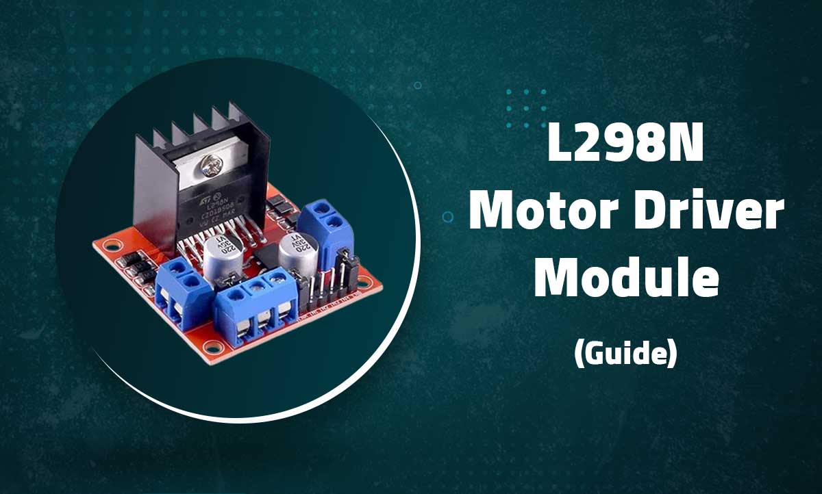
L298N Motor Driver Module
2A Dual Channel H-Bridge for DC and Stepper Motors
Introduction
The L298N is a high-voltage, high-current dual full-bridge driver designed to control inductive loads like DC motors and stepper motors. This module can drive two DC motors bidirectionally or one stepper motor with up to 2A per channel.

Key Features
High Power
2A continuous current per channel
Bidirectional
Full control of two DC motors
Wide Voltage
5V-35V operating range
Multiple Control
PWM speed + direction control
Technical Specifications
| Driver IC | L298N Dual H-Bridge |
|---|---|
| Operating Voltage | 5V – 35V DC |
| Peak Current | 3A per channel (2A continuous) |
| Logic Voltage | 5V (compatible with 3.3V MCUs) |
| PWM Frequency | Up to 25kHz |
| Power Dissipation | 25W (with heatsink) |
| Control Signals | TTL/CMOS compatible |
| Dimensions | 43mm × 43mm × 27mm |
Pin Configuration

| Terminal | Function | Connection |
|---|---|---|
| +12V | Motor Power (5-35V) | Battery positive |
| GND | Ground | Battery negative |
| +5V | Logic Power (optional) | 5V (if jumper removed) |
| ENA | Channel A Enable | PWM capable pin |
| IN1/IN2 | Channel A Control | Digital pins |
| IN3/IN4 | Channel B Control | Digital pins |
| ENB | Channel B Enable | PWM capable pin |
| OUT1/OUT2 | Channel A Motor | Motor A terminals |
| OUT3/OUT4 | Channel B Motor | Motor B terminals |
Note: Keep the jumper on +5V terminal if using the onboard 5V regulator
Wiring Diagrams
Dual DC Motor Control

// Connections:
// +12V → Battery positive (7V-35V)
// GND → Battery negative
// ENA → D9 (PWM)
// IN1 → D8
// IN2 → D7
// ENB → D10 (PWM)
// IN3 → D6
// IN4 → D5
// OUT1/OUT2 → Motor A
// OUT3/OUT4 → Motor B
Stepper Motor Control

// Connections for 4-wire bipolar stepper:
// +12V → Appropriate voltage for stepper
// OUT1 → Coil 1+
// OUT2 → Coil 1-
// OUT3 → Coil 2+
// OUT4 → Coil 2-
// ENA & ENB → Always HIGH (jumper in place)
Basic DC Motor Control
// Motor A connections
const int enA = 9;
const int in1 = 8;
const int in2 = 7;

void setup() {
  pinMode(enA, OUTPUT);
  pinMode(in1, OUTPUT);
  pinMode(in2, OUTPUT);

  // Initial state - motor off
  digitalWrite(in1, LOW);
  digitalWrite(in2, LOW);
}

void loop() {
  // Rotate clockwise at full speed
  digitalWrite(in1, HIGH);
  digitalWrite(in2, LOW);
  analogWrite(enA, 255); // Full speed
  delay(2000);

  // Rotate counter-clockwise at half speed
  digitalWrite(in1, LOW);
  digitalWrite(in2, HIGH);
  analogWrite(enA, 128); // Half speed
  delay(2000);

  // Motor brake
  digitalWrite(in1, HIGH);
  digitalWrite(in2, HIGH);
  delay(1000);

  // Motor stop
  digitalWrite(in1, LOW);
  digitalWrite(in2, LOW);
  delay(1000);
}
Stepper Motor Control
const int stepsPerRevolution = 200; // Change for your stepper
const int in1 = 8, in2 = 7, in3 = 6, in4 = 5;
int stepDelay = 5; // ms between steps

void stepMotor(int step) {
  switch(step) {
    case 0:  // 1000
      digitalWrite(in1, HIGH);
      digitalWrite(in2, LOW);
      digitalWrite(in3, LOW);
      digitalWrite(in4, LOW);
      break;
    case 1:  // 1100
      digitalWrite(in1, HIGH);
      digitalWrite(in2, HIGH);
      digitalWrite(in3, LOW);
      digitalWrite(in4, LOW);
      break;
    case 2:  // 0100
      digitalWrite(in1, LOW);
      digitalWrite(in2, HIGH);
      digitalWrite(in3, LOW);
      digitalWrite(in4, LOW);
      break;
    case 3:  // 0110
      digitalWrite(in1, LOW);
      digitalWrite(in2, HIGH);
      digitalWrite(in3, HIGH);
      digitalWrite(in4, LOW);
      break;
    case 4:  // 0010
      digitalWrite(in1, LOW);
      digitalWrite(in2, LOW);
      digitalWrite(in3, HIGH);
      digitalWrite(in4, LOW);
      break;
    case 5:  // 0011
      digitalWrite(in1, LOW);
      digitalWrite(in2, LOW);
      digitalWrite(in3, HIGH);
      digitalWrite(in4, HIGH);
      break;
    case 6:  // 0001
      digitalWrite(in1, LOW);
      digitalWrite(in2, LOW);
      digitalWrite(in3, LOW);
      digitalWrite(in4, HIGH);
      break;
    case 7:  // 1001
      digitalWrite(in1, HIGH);
      digitalWrite(in2, LOW);
      digitalWrite(in3, LOW);
      digitalWrite(in4, HIGH);
      break;
  }
}

void setup() {
  pinMode(in1, OUTPUT);
  pinMode(in2, OUTPUT);
  pinMode(in3, OUTPUT);
  pinMode(in4, OUTPUT);
}

void loop() {
  // Rotate CW
  for(int i=0; i<stepsPerRevolution; i++) { stepMotor(i % 8); delay(stepDelay); } delay(1000); // Rotate CCW for(int i=stepsPerRevolution; i>0; i--) {
    stepMotor(i % 8);
    delay(stepDelay);
  }

  delay(1000);
}
Tip: For better performance, use the AccelStepper library instead of manual stepping
Advanced Features
Current Sensing
float readCurrent(int sensorPin) {
  int rawValue = analogRead(sensorPin);
  float voltage = rawValue * (5.0 / 1023.0);
  float current = voltage / 0.1; // 0.1Ω sense resistor
  return current;
}

void checkOverCurrent() {
  if(readCurrent(A0) > 2.0) { // 2A threshold
    digitalWrite(enA, LOW); // Emergency stop
    Serial.println("OVER CURRENT!");
  }
}
Acceleration Control
void smoothStart(int motorPin) {
  for(int i=0; i<=255; i+=5) { analogWrite(motorPin, i); delay(50); } } void smoothStop(int motorPin) { for(int i=255; i>=0; i-=5) {
    analogWrite(motorPin, i);
    delay(50);
  }
}
Serial Control
void processSerialCommands() {
  if(Serial.available()) {
    char cmd = Serial.read();
    switch(cmd) {
      case 'F': // Forward
        digitalWrite(in1, HIGH);
        digitalWrite(in2, LOW);
        break;
      case 'B': // Backward
        digitalWrite(in1, LOW);
        digitalWrite(in2, HIGH);
        break;
      case 'S': // Stop
        digitalWrite(in1, LOW);
        digitalWrite(in2, LOW);
        break;
      case '0'...'9': // Speed 0-9
        int speed = map(cmd-'0', 0, 9, 0, 255);
        analogWrite(enA, speed);
        break;
    }
  }
}
Troubleshooting
Motor Not Moving
- Check enable jumpers are in place
- Verify motor power supply is adequate
- Test with direct battery connection
Overheating
- Ensure heatsink is properly attached
- Reduce current draw (smaller motors)
- Add cooling fan if needed
Erratic Behavior
- Add 100μF capacitor across motor terminals
- Separate logic and motor power supplies
- Check for loose connections
Related Posts
MG90S Mini Digital 180° Servo
MG90S Mini Digital 180° Servo
Metal Gear, 2.2kg·cm Torque for RC and Robotics
Introduction
...

Flex Sensor 5.6 cm (Detect Bending Motion)
Flex Sensor 5.6cm
Bend Detection Sensor for Arduino and Wearable Electronics Projects
...
Guide for HC-SR04 Ultrasonic Distance Sensor Module
HC-SR04 Ultrasonic Distance Sensor Module
Precise Non-Contact Distance Measurement for Arduino Projects
Guide to 5-Channel Flame Sensor Module
5-Channel Flame Sensor Module
Multi-directional Flame Detection for Arduino and Robotics Projects

Recent Comments