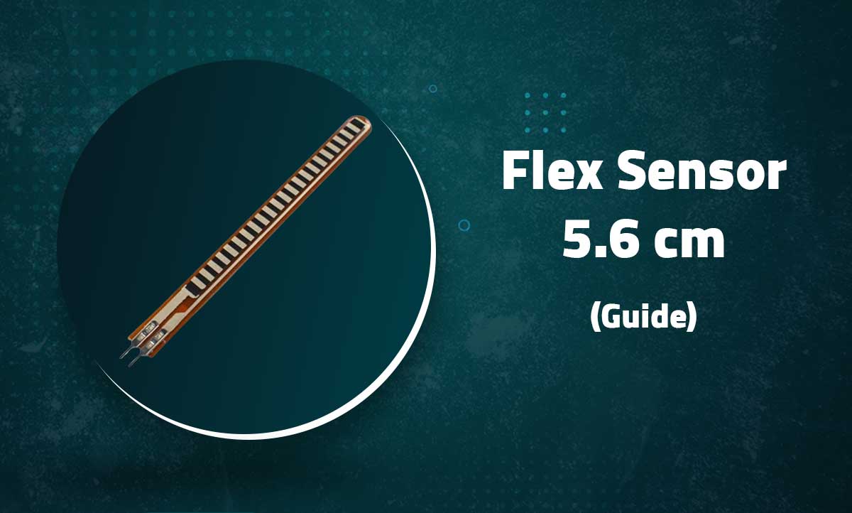
Flex Sensor 5.6cm
Bend Detection Sensor for Arduino and Wearable Electronics Projects
Introduction
The 5.6cm Flex Sensor is a variable resistor that changes resistance when bent. Perfect for detecting finger movements in gloves, robotic joints, or any application requiring bend measurement.
Key Features
Bend Sensing
10KΩ to 40KΩ resistance range
Compact Size
5.6cm active sensing length
Simple Interface
Analog voltage output
Wearable
Ideal for glove-based controls
Technical Specifications
| Resistance Range | 10KΩ (flat) to 40KΩ (90° bend) |
|---|---|
| Active Length | 5.6cm (2.2 inches) |
| Width | 6.4mm (0.25 inches) |
| Thickness | 0.5mm (flat) |
| Bend Radius | 12.7mm minimum |
| Operating Voltage | 3.3V – 5V DC |
| Lifetime | 1 million+ bends |
| Temperature Range | -35°C to +80°C |
Pin Configuration
| Wire Color | Description | Connection |
|---|---|---|
| Black | Ground | GND |
| Red | Signal | Analog Pin (with voltage divider) |
Note: Requires a voltage divider circuit (10KΩ resistor recommended)
Basic Wiring with Arduino

// Voltage Divider Circuit:
// Flex Sensor → A0
// 10KΩ Resistor between A0 and VCC
// GND → Flex Sensor other terminal
Basic Bend Detection
const int flexPin = A0;

void setup() {
  Serial.begin(9600);
}

void loop() {
  int flexValue = analogRead(flexPin);
  Serial.print("Sensor Value: ");
  Serial.println(flexValue);

  if(flexValue > 800) {
    Serial.println("Fully Bent");
  } else if(flexValue > 500) {
    Serial.println("Partially Bent");
  } else {
    Serial.println("Flat Position");
  }

  delay(500);
}
Advanced Calibration
// Calibration values (adjust based on your sensor)
#define FLAT_RESISTANCE 10000  // 10KΩ when flat
#define BEND_RESISTANCE 40000  // 40KΩ when bent 90°
#define R_DIVIDER 10000        // 10KΩ resistor value

void setup() {
  Serial.begin(9600);
}

void loop() {
  int flexADC = analogRead(A0);
  float flexV = flexADC * 5.0 / 1023.0;
  float flexR = R_DIVIDER * (5.0 / flexV - 1.0);

  // Map resistance to bend angle (0°-90°)
  float angle = map(flexR, FLAT_RESISTANCE, BEND_RESISTANCE, 0, 90);
  angle = constrain(angle, 0, 90);

  Serial.print("Resistance: ");
  Serial.print(flexR/1000, 1);
  Serial.print("KΩ\tAngle: ");
  Serial.print(angle, 0);
  Serial.println("°");

  delay(500);
}
Calibration Tip: Record sensor values at known bend angles for best accuracy
Advanced Applications
Gesture Control
int lastFlexValue = 0;

void detectGesture() {
  int currentFlex = analogRead(A0);
  int delta = currentFlex - lastFlexValue;

  if(abs(delta) > 100) { // Threshold
    if(delta > 0) {
      Serial.println("Bending detected");
    } else {
      Serial.println("Straightening detected");
    }
  }
  lastFlexValue = currentFlex;
}
Multiple Sensors
const int numSensors = 5;
const int flexPins[] = {A0, A1, A2, A3, A4};

void readAllSensors() {
  for(int i=0; i<numSensors; i++) {
    int val = analogRead(flexPins[i]);
    Serial.print("Finger ");
    Serial.print(i);
    Serial.print(": ");
    Serial.println(val);
  }
}
Wireless Data
#include <SPI.h>
#include <nRF24L01.h>
#include <RF24.h>

RF24 radio(7, 8); // CE, CSN pins
const byte address[6] = "00001";

void setup() {
  radio.begin();
  radio.openWritingPipe(address);
  radio.setPALevel(RF24_PA_MIN);
  radio.stopListening();
}

void loop() {
  int flexData = analogRead(A0);
  radio.write(&flexData, sizeof(flexData));
  delay(20);
}
Troubleshooting
Unstable Readings
- Ensure secure wiring connections
- Add 0.1μF capacitor across sensor leads
- Use shorter wires between sensor and Arduino
No Change in Values
- Verify voltage divider circuit is properly connected
- Check for sensor damage (visible cracks)
- Test with known resistor values
Limited Range
- Adjust the voltage divider resistor value
- Recalibrate for your specific bend range
- Check power supply stability
Related Posts
MG90S Mini Digital 180° Servo
MG90S Mini Digital 180° Servo
Metal Gear, 2.2kg·cm Torque for RC and Robotics
Introduction
...
XKC-Y25-V Non-Contact Water Liquid Level Sensor
XKC-Y25-V Non-Contact Water Liquid Level Sensor
Capacitive Detection Without Physical Contact
...
Waterproof Ultrasonic Obstacle Sensor, Sensor with Separate Probe
+
Waterproof Ultrasonic Obstacle Sensor
Distance Measurement with Separate Waterproof Probe
...
Water Level Depth Detection Sensor
Water Level Depth Detection Sensor
Liquid Measurement for Arduino and IoT Projects
Introduct...
VL53L0X Purple Laser Distance Sensor Module
VL53L0X Laser Distance Sensor Module
High-Speed, High-Precision Time-of-Flight Distance Measurement
...
TCS34725 RGB Color Sensor Module
TCS34725 RGB Color Sensor Module
High-Accuracy Digital Color Detection with IR Filter
Introd...
TCS3200 Color Sensor Module
TCS3200 Color Sensor Module
Precise RGB Color Detection for Arduino and Embedded Projects
In...
PN532 NFC RFID Read/Write Module V3 Kit
PN532 NFC RFID Read/Write Module V3 Kit
Advanced Near Field Communication for Arduino and Embedded Systems
...
HC-SR501 PIR Motion Sensor Module
HC-SR501 PIR Motion Sensor Module
Passive Infrared Detection for Security and Automation Projects
ACS712 Current Sensor Module
ACS712 5A Current Sensor Module
Hall-Effect Based AC/DC Current Measurement for Arduino Projects

AS608 Optical Fingerprint Sensor Module
AS608 Optical Fingerprint Sensor Module
High-Precision Biometric Recognition for Arduino and Microcontroller P...

Recent Comments